Metadata driven architectures powers solutions or product by decomposing the metadata definitions instead of using data definitions for defining ETL or ELT flows.
In the data world, we tend to focus more on data driven solutions and architecture models. However, the metadata driven architecture has been widely adopted in product architectures and has been established as a flexible and resilient model that suits many product architectures.
Why not shift the attention now , to metadata driven solutions instead of data driven solutions? In a metadata driven solution, detailed attention is paid to how the data is stored on a platform and how can it be referred to without the complications of referential integrities. The focus is more on building reusable solutions without being disrupted by changes. Maybe it’s time we accept change as an integral part of a solution lifecycle. Keeping change in mind, every solution will need to cater for the scenario where the metadata or data might change.
For every such change, should we create a change and release management lifecycle? How about building solutions that will foresee change and will adapt to future changes.
Some advantages of a metadata driven architecture are
-
Future proof solutions for minor fixes and changes to the platform/solution/enterprise
-
Create more saleable and resilient transformation during an ETL/ELT flow to minimise the effect of data changes
-
Add and remove components of a solution without triggering a full-fledged engineering and release management life cycle
-
Reduce dependencies on IT expertise in any particular tool or technology to manage changes to existing pipelines
-
Improve the cost efficiency of every engineering effort that goes into building the foundation of a metadata driven solution.
-
The metadata driven model generates a shift in the uniform development process , wherein business analysts and data engineers use the same set of variants to build the solution. This leads to a democratic consumption of data.
-
Create fluid data models like a fluid data vault structure can be enabled by using a metadata driven architecture
How do we implement a metadata driven solution?
To implement this architecture we will need to define data structures similar to those shown in the below diagram.
The Zetaris Networked Data Platform has been used to capture the meta information of various source systems like streaming distributions(Apache Kafka) , SQL/NoSQL databases , API applications and the possible addition of AWS Glue in future
The incoming meta information results in the creation of the driver entities i.e the Metadata entity and the Data entity. The metadata entity is a physical entity which stores the source objects and their schema, relationships and status in a conformed model. The Data Entity is a virtual object that established virtual connections via the Zetaris platform and allows for searchable and analytics focused information retrieval from source.
These drivers are then used to create various solutions like Data Quality and Data Provisioning solutions.
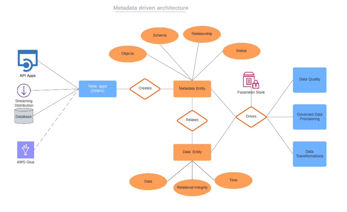
Any future additions to source systems is handled via parameters and follow the same metadata model and storage patterns. Hence to add new sources to the Data Quality solution , it will require no major changes other than including the newly added information to the parameter store.
Use-cases where metadata driven architectures automates the ETL process
-
In dealing with CRM systems like Salesforce where customers entities or system entities follow a proper naming convention. In such systems , the metadata of additional source systems can be inferred based on a pattern that the CRM system has already adopted
-
The Raw Data Store maintained in data vaults can also be populated with these techniques as the data does not undergo transformation and the metadata can be used to redirect data from the source systems into the relevant hubs and satellites. This eliminates the need for engineering involvement every time a new source has to be brought into the integration.
-
Repetitive rules based engines for data models that rely on a pattern for application of rules also benefit tremendously when they are metadata driven. This allows for easy manipulation of the engine without disturbing the actual rules.
|
Cost Factor |
Reason for Cost |
Traditional ETL |
Metadata driven |
|---|---|---|---|
|
Software |
Organisations can have varying needs from an ETL platform. In case a reporting tool and associated ETL tools are already being used across the organisation , it is preferred to opt for a standalone software. With an Integrated software , the end-to-end BI platform can be opted for and is more suited to organisations who are looking for a suite of features. |
Standalone Software=20% Integrated ETL =45% |
Metadata apps like Zetaris =20% |
|
Hardware |
Workstations for the initial ETL programming and servers (either on premises or in the cloud) on which to host the source data and target data repositories. Compute for the ETL processing itself, will be needed. |
On-prem infrastructure = 30% Cloud infrastructure =40% (inclusive of storage) |
On-prem infrastructure = 20% Cloud infrastructure =30% (no need for ETL storage) |
|
Consulting |
A discovery cost to help manage post-implementation ETL processes. |
Discovery cost =20% |
Discovery cost = 10% |
|
Maintenance |
Recurring costs for the ETL processes needs to be factored into ongoing maintenance costs to find your ETL's total cost of ownership (TCO). TCO is dealt in different ways depending on the budget. Organisations may opt in for a one-time license cost or hire consultants for ongoing maintenance or upskill and train internal resources which becomes very cost effective in the long run |
One -time license =20% Consultants hired = 30% Internal staff =25% |
One -time license =20% Consultants hired = 10% Internal staff =10% |
|
Training |
Training becomes important if the strategy is to maintain the application internally. The ease of use of the software, reduces the training needs required to get developers up to speed. It becomes important for an ETL tool to connects to a wide variety of relational databases which will result in reduced training costs. |
Training cost =20% |
Training cost =5% |
|
Development |
In case of change management, it will be necessary to factor the opportunity cost of diverting efforts into maintaining changes to the data models or business rules. The product allowing for parameterisation and pattern matching mechanism reduces development cost by reducing efforts involved in changes. |
Developer cost =30% |
Developer Cost =10% |
Using these meta modelling techniques , enterprises can be enabled to deploy multiple solutions using the same underlying infrastructure and resilient meta models . This makes the data solution lifecycle tremendously short allowing users to access their data quickly and without the hassle of a full-blown engineering intervention.
Zetaris Implementation Process
Pre-requisites:
-
Zetaris must have its metastore DB registered on the Lightning UI with a given name “metastore”.
-
JDBC credentials for the “metastore” datasource should be provided.
-
Source and Target datasource connections should be present on the Zetaris UI.
-
Tables in the source and target datasource should have the same schema.
-
The cdc pipeline names should be prefixed with ‘cdc_’ in the parameter store CSV file.
Please Note:
1. The steps mentioned on this page use the source tables from the File Sources (CSV Files). Instead of CSV files, we can use any other data source (e.g. PostgresSQL, Snowflake, etc.).
2. On this page, ‘rds_file’ is the source database, and ‘rds’ is the target database. Also, the CDC pipelines will be created for the tables ‘test_table_1’, ‘test_table_2’, ‘test_table_3’, and ‘test_table_4’.
Flow Diagram
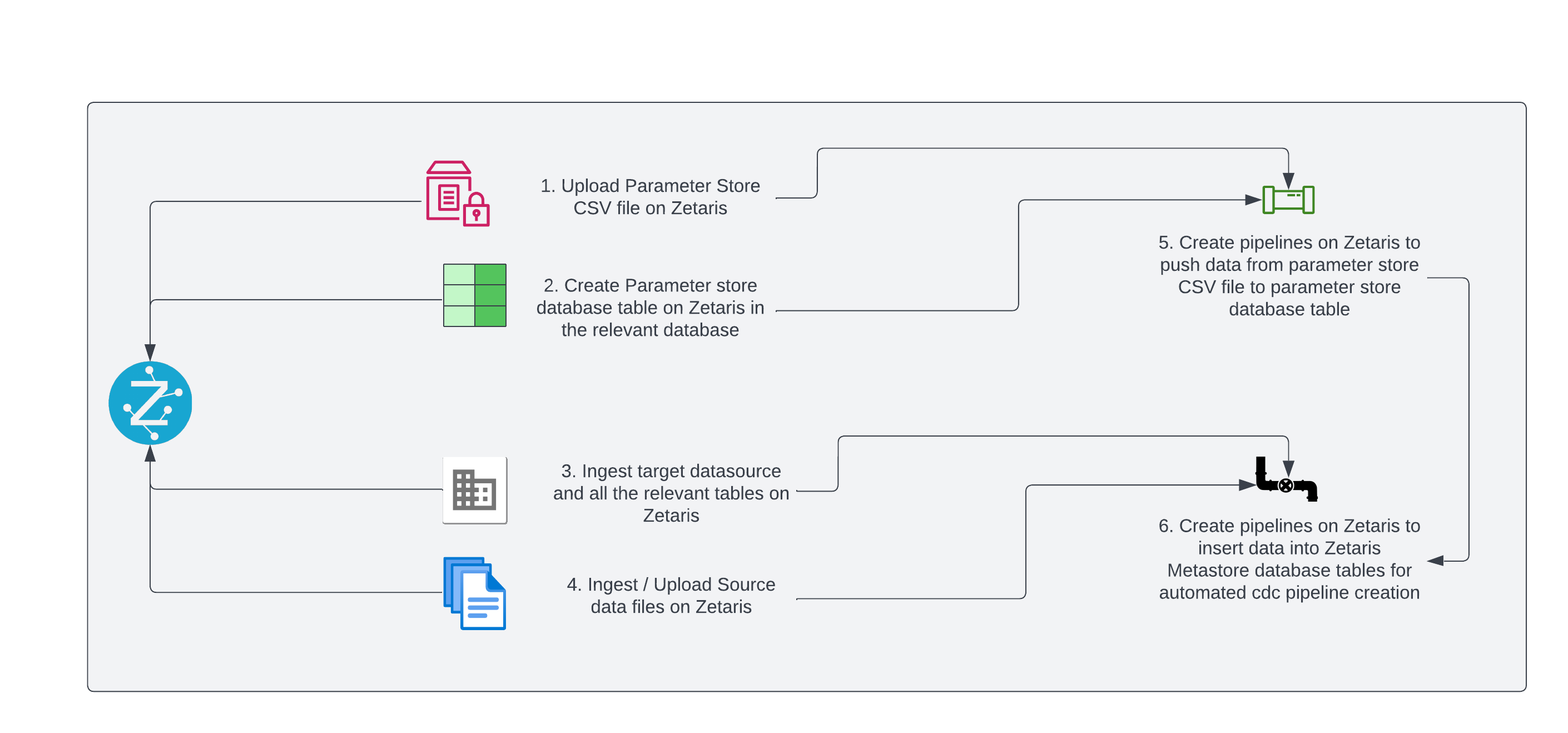
Pipeline Creation Steps:
Step 1:
Create the Parameter Store CSV file in the below format.
source_datasource_name,table_name,pipeline_name,target_datasource_name
rds_file,test_table_1,cdc_test_table_1,rds
rds_file,test_table_2,cdc_test_table_2,rds
rds_file,test_table_3,cdc_test_table_3,rds
rds_file,test_table_4,cdc_test_table_4,rds
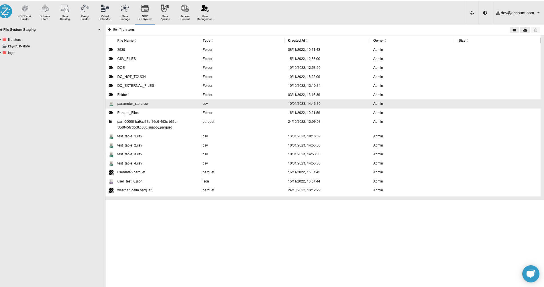
Step 2:
Upload the Parameter Store CSV file on Zetaris UI using the NDP File Store.
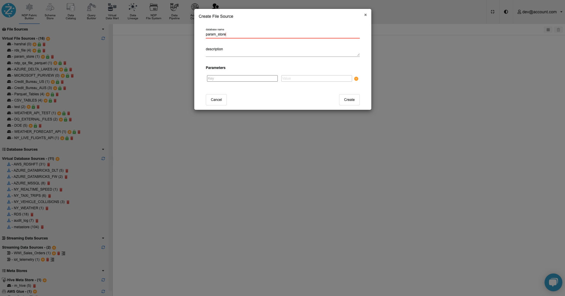
Step 3:
Create a virtual file source named ‘param_store’ using the NDP Fabric Builder on Zetaris UI.
Step 4:
On the Zetaris UI, inside the ‘param_store’ database, register the ‘parameter_store.csv' file as a table named 'parameter_store’.
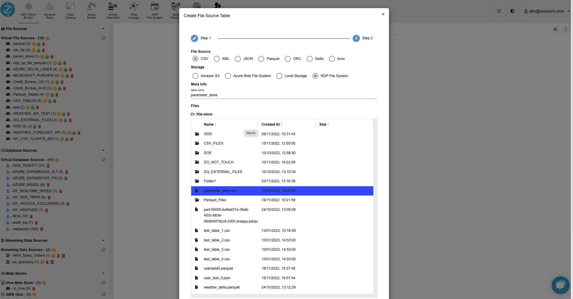
Step 5:
Using the schema store view tab on Zetaris UI, create a database table ‘parameter_store’ in any relevant datasource & register the datasource.
create table parameter_store
(
  id serial,
  source_datasource_name text,
  table_name text,
  pipeline_name text,
  target_datasource_name
) using rds;


register datasource tables from rds;
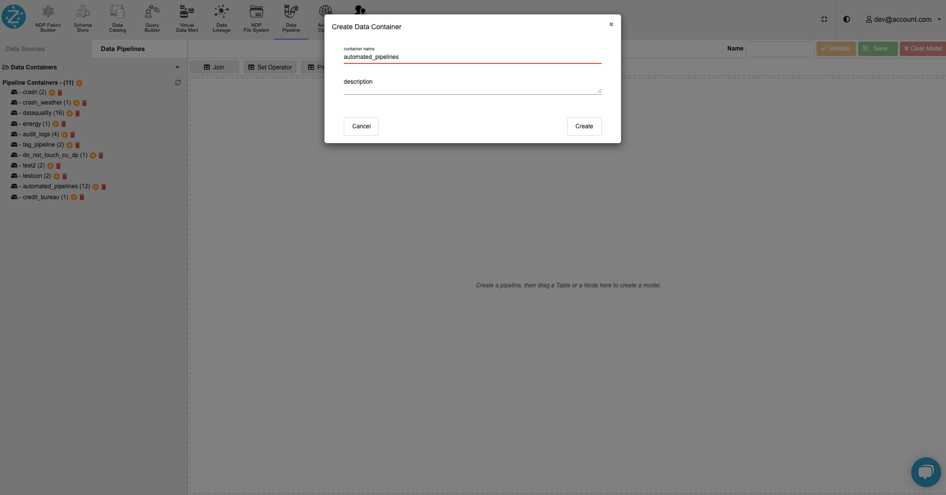
Step 6:
Create a pipeline container named ‘automated_pipelines’ using the Data Pipelines tab on the Zetaris UI.
Please Note: Zetaris Team can assist to migrate the below pipelines.
Step 7:
Inside the ‘automated_pipelines’ container, create a pipeline named ‘param_store’ to populate data into the database table from the Parameter Store CSV file.
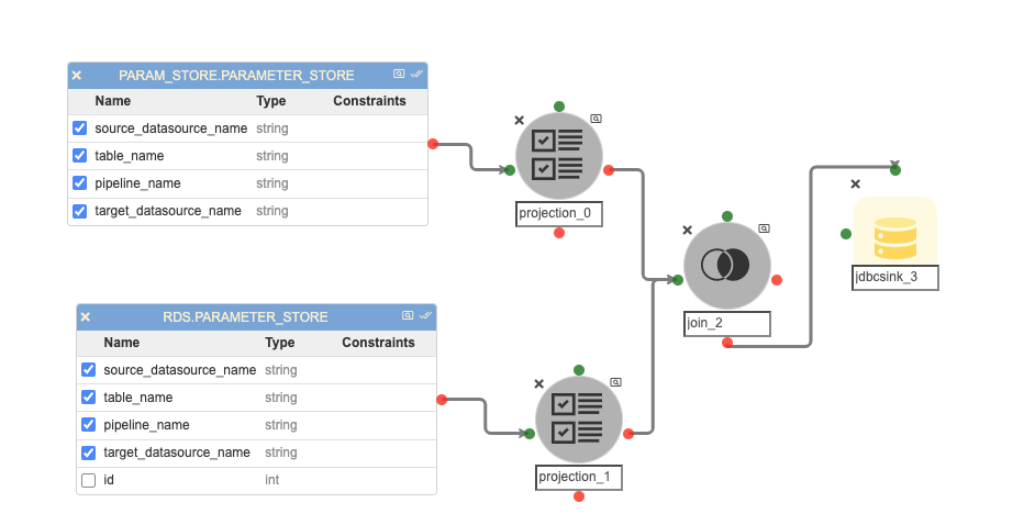
Possible changes in this pipeline:
-
The ‘RDS.PARAMETER_STORE’ could be different if the user has registered the parameter store table in any other database.
-
The JDBC connection credentials for the ‘RDS.PARAMETER_STORE’ table in the JDBC Sink Node named ‘jdbcsink_3’.
Step 8:
Inside the ‘automated_pipelines’ container, create a pipeline named ‘pipe_rel_inserts’ to populate data into the ‘pipeline_relation’ Metastore database table that stores the name of the pipelines.
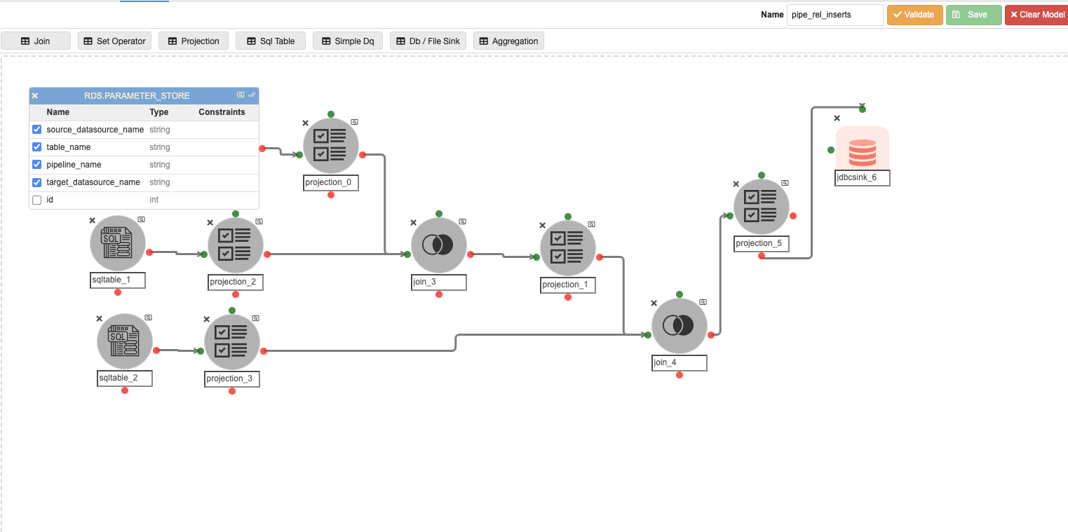
Possible changes in this pipeline:
-
The ‘RDS.PARAMETER_STORE’ could be different if the user has registered the parameter store table in a different database.
-
The value of the virtual column named ‘container_name’ in ‘projection_0’ will change if the user has any other pipeline container name other than ‘automated_pipelines’.
-
The SQL query in ‘sqltable_2’, if the user has any other pipeline container name other than ‘automated_pipelines’.
-
The join predicate in ‘join_4’, if the user has any other pipeline container name other than ‘automated_pipelines’.
-
The JDBC connection credentials for the ‘metastore.pipeline_relation’ table in the JDBC Sink Node named ‘jdbcsink_6’.
Step 9:
Inside the ‘automated_pipelines’ container, create a pipeline named ‘pipe_node_inserts’ to populate data into the ‘pipeline_node’ Metastore database table that stores the information about the nodes inside the CDC pipelines.
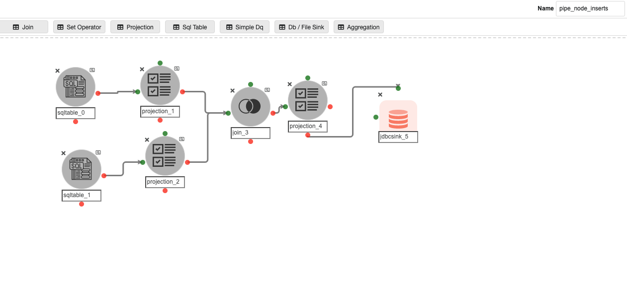
Possible changes in this pipeline:
-
The SQL query in ‘sqltable_0’ and ‘sqltable_1’, if the user has any pipeline container name other than ‘automated_pipelines’.
-
The join predicate in ‘join_3’, if the user has the pipeline container name other than ‘automated_pipelines’.
-
The JDBC connection credentials for the ‘metastore.pipeline_node’ table in the JDBC Sink Node named ‘jdbcsink_5’.
Step 10:
Inside the ‘automated_pipelines’ container, create a pipeline named ‘pipeline_sql_node_inserts’ to populate data into the ‘pipeline_sqltable’ Metastore database table that stores the information about the SQL Table nodes inside the CDC pipelines.
Possible changes in this pipeline:
-
The SQL query in ‘sqltable_0’ and ‘sqltable_1’, if the user has any pipeline container name other than ‘automated_pipelines’.
-
The ‘RDS.PARAMETER_STORE’ in ‘sqltable_0’ could be different if the user has registered the parameter store table in any other database.
-
The JDBC connection credentials for the ‘metastore.pipeline_sqltable’ table in the JDBC Sink Node named ‘jdbcsink_9’.
Step 11:
Inside the ‘automated_pipelines’ container, create a pipeline named ‘pipeline_proj_inserts’ to populate data into the ‘pipeline_projection’ Metastore database table that stores the information about the Projection nodes inside the CDC pipelines.
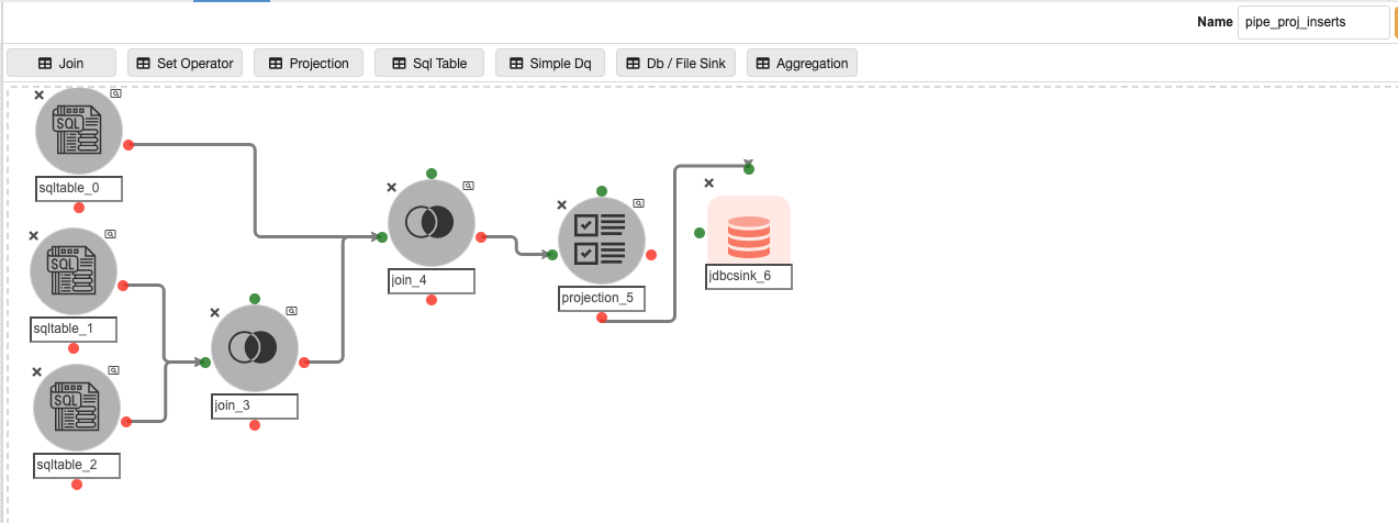
Possible changes in this pipeline:
-
The SQL query in ‘sqltable_0’ and ‘sqltable_1’, if the user has any pipeline container name other than ‘automated_pipelines’.
-
The ‘RDS.PARAMETER_STORE’ in ‘sqltable_0’ could be different if the user has registered the parameter store table in any other database.
-
The JDBC connection credentials for the ‘metastore.pipeline_projection’ table in the JDBC Sink Node named ‘jdbcsink_6’.
Step 12:
Inside the ‘automated_pipelines’ container, create a pipeline named ‘pipeline_join_inserts’ to populate data into the ‘pipeline_join ’ Metastore database table that stores the information about the Join nodes inside the CDC pipelines.
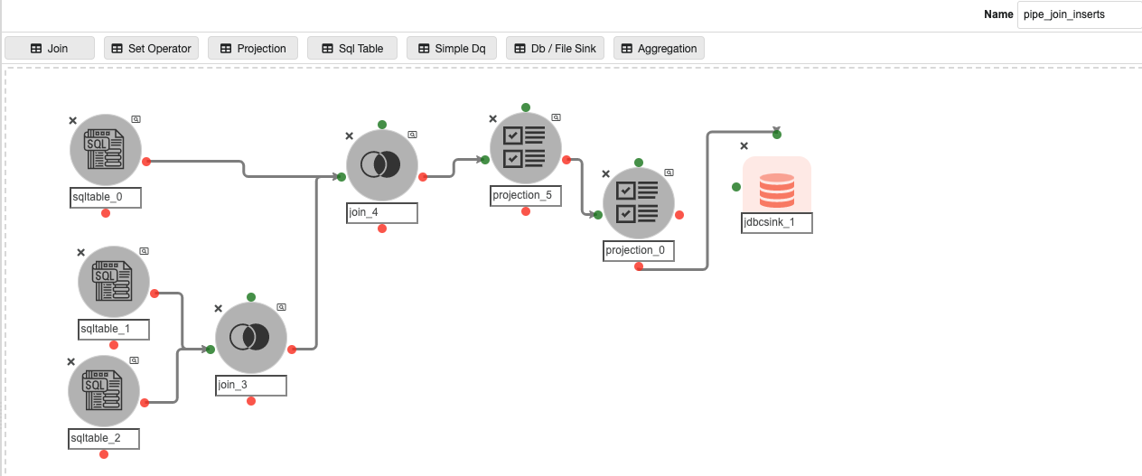
Possible changes in this pipeline:
-
The SQL query in ‘sqltable_0’ and ‘sqltable_1’, if the user has any pipeline container name other than ‘automated_pipelines’.
-
The ‘RDS.PARAMETER_STORE’ in ‘sqltable_0’ could be different if the user has registered the parameter store table in any other database.
-
The JDBC connection credentials for the ‘metastore.pipeline_join’ table in the JDBC Sink Node named ‘jdbcsink_1’.
Step 13:
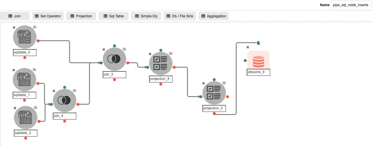
Inside the ‘automated_pipelines’ container, create a pipeline named ‘pipeline_node_schema_inserts’ to populate data into the ‘pipeline_node_schema ’ Metastore database table that stores the information about the Join nodes inside the CDC pipelines.
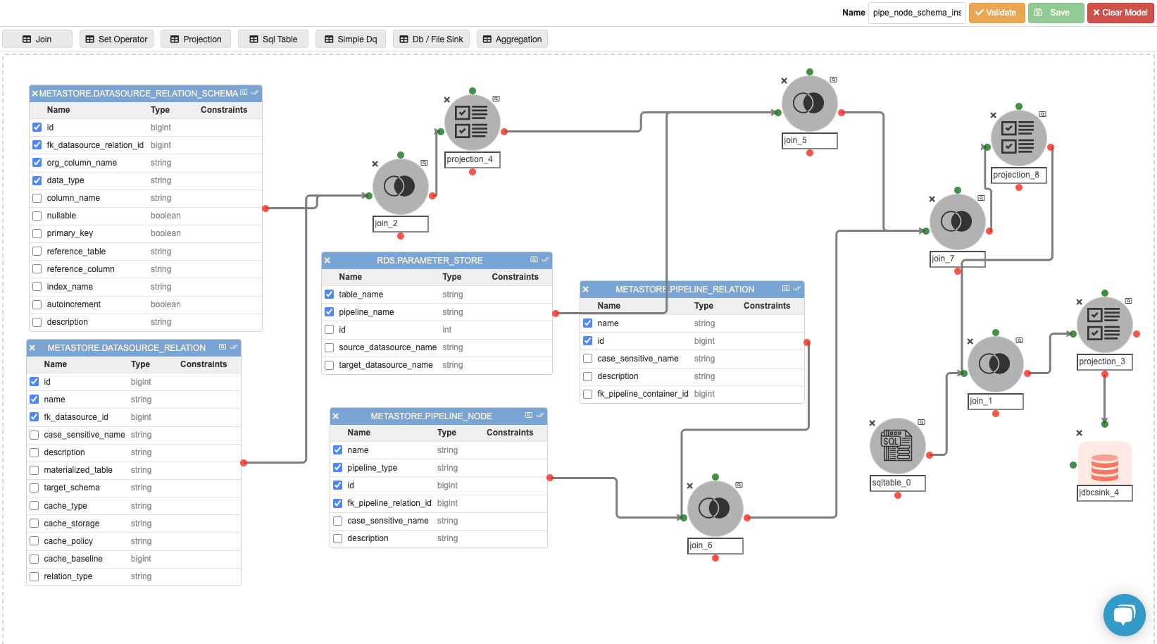
Possible changes in this pipeline:
-
The ‘RDS.PARAMETER_STORE’ could be different if the user has registered the parameter store table in any other database.
-
The SQL query in ‘sqltable_0’, if the user has any pipeline container name other than ‘automated_pipelines’.
-
The join predicate in ‘join_5’ and ‘join_7’, if the user has any other database where parameter store exists, instead of ‘RDS.PARAMETER_STORE’.
-
The value of the virtual column named ‘con_name’ in ‘projection_8’ if the user has any pipeline container name other than ‘automated_pipelines’.
-
The join predicate in ‘join_1’, if the user has any pipeline container name other than ‘automated_pipelines’.
-
The JDBC connection credentials for the ‘metastore.pipeline_node_schema’ table in the JDBC Sink Node named ‘jdbcsink_4’.
Step 14:
Inside the ‘automated_pipelines’ container, create a pipeline named ‘pipeline_md5_inserts’ to populate data into the ‘pipeline_node_schema ’ Metastore database table that stores the information about the virtual columns stored in projection nodes which are created to store the md5 hash of all columns in a table to capture the delta data between source and target table.
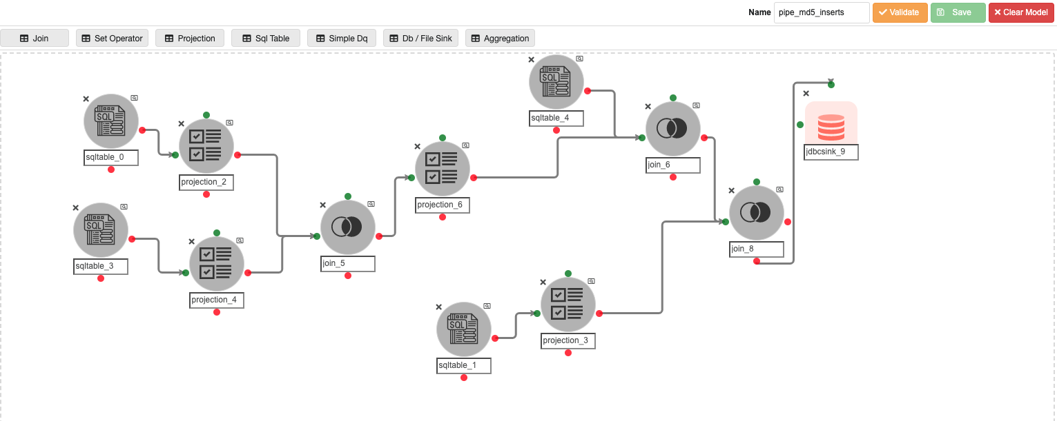
Possible changes in this pipeline:
-
The SQL query in ‘sqltable_0’ and ‘sqltable_3’, if the user has any pipeline container name other than ‘automated_pipelines’.
-
The join predicate in ‘join_5', if the user has any other pipeline container name other than ‘automated_pipelines’.
-
The SQL query in ‘sqltable_1’, if the user has any other database where parameter store exists, instead of ‘RDS.PARAMETER_STORE’ and target database has any name other than ‘RDS’.
-
The JDBC connection credentials for the ‘metastore.pipeline_node_schema’ table in the JDBC Sink Node named ‘jdbcsink_9’.
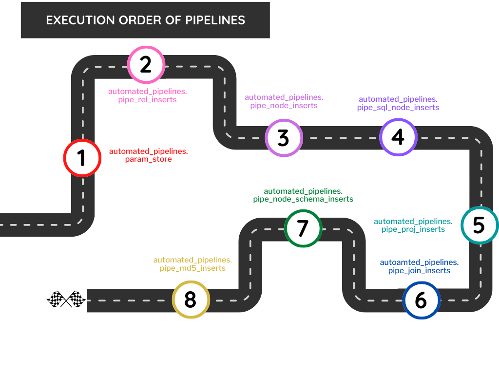
Pipeline Execution Steps
Once all the pipelines are created, we need to execute the pipelines in a specified order to avoid the primary and foreign key violation errors.
The below image shows the order in which the pipelines need to be executed:
Walkthrough of automated CDC Pipelines Creation Process (Video)